Thursday, April 16, 2015

VATS Bypass

See this post for background:  Keys

I cut the 2 white wires on the steering column side of the connector and added the resistor.


To protect this little thing it was then liberally wrapped with heat shrink tubing, tape, and flex conduit.  This is the connector and resistor installed back in vehicle but before it was tucked up with the other dash wires.  Final positioning can be seen here.


Dash Wires


Treasure hunt - try to find all items listed here.  Hint: use red arrows.

  1. Yellow connector for air bag - DO NOT DISCONNECT!
  2. Black connector with purple and white wires on one side and white on other.  White wires go up the steering column to key cylinder for VATS security system.  White wires will be cut and connected to a resistor as per the 'VATS Bypass'.
  3. Yellow wire with 2 butt splices and a twisted/taped splice.
  4. Old blue wire tap on red wire
  5. Old taped wire tap on red wire
  6. Old unprotected wire tap on pink wire.  This has less then half the wristbands still intact.
  7. Old taped wire tap on pink wire.
  8. Old taped wire tap on white wire.
  9. Old unused ground screw.

I think most of these are from previous radio and/or alarm installs.  Going to try and knock all these out next (tomorrow?).

4/16/15 Update:
All tape was removed.  Some taps were soldered and did not nick the conductor.  These were coated with 'liquid tape' and wrapped with real tape.  Other taps were replace with butt splice because conductors were cut.  Undersized wire was replaced.


Horn


This wire runs up the steering column to the steering wheel horn button.  It was already damaged.  The horn button or the wire to it is not working.  If I jump this wire to ground, it activates the horn relay and the horns sound.  This wire will be routed to a push button on the dash then grounded to dash frame.

4/16/15 Update:
Horn button installed in dash where previous owner had cut hole for something.

Blue wire was run to button in dash then to ground.


Tuesday, April 14, 2015

Doors


Both doors have been re-worked:

  • new inner and outer felts around window
  • new gasket around door
  • lubed window mechanism
  • lubed lock/latch
Drivers door cannot be locked with key.  Rest of locks and latches work as normal.

Coolant Temp Sensor and Fuel Lines

After
Before
Found another disconnected sensor.  It is was the temp sensor on the front of the drivers side head with a single wire going to it.  Sensor is right arrow in 'before' pic.  This one just runs the gauge on the dash.  It would not have any effect on the drivability.  The sensor connection tab was painted and bent.  I cleaned and straightened it.  Gauge is now working.

Also noticed a disconnected clamp on the fuel lines (upper left arrow).  Further research determined it is function is to limit vibration damage to the metal fuel lines.  The bracket to hold it is missing - probably for some time.  One is on order from eBay.  For now, I wired it up with 12awg household wire.

Wiring harness was also under protected and a little too close to the exhaust manifold (lower left arrow).  I put some flex conduit over to for abrasion protection and wired it back - away from manifold - sort of visible in after pic.

4/14/15 Update:
Fuel line bracket arrived and was installed.
Fuel Line bracket installed.


Monday, April 13, 2015

More Free Stuff


Went to yard again for more free miscellaneous fasteners.

The trim clips were so brittle they broke when I tried to use them.

Thursday, April 9, 2015

IAT - Intake Air Temperature sensor


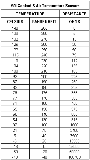
Reviewing the TunerPro RT logs, I noticed the MAT (Manifold Air Temp) was reporting >200F temps - that seemed too high.  This sensor is in the air filter canister and is commonly referred to as the IAT - Intake Air Temp sensor.  Found this chart to test it.  The error in resistance seemed to line up with the high temps in the logs.  Room temp, ~80 degrees, had 600-1200 ohms resistance which would place it too high in the temp chart.  New sensor was ordered for ~$21.

I had trouble getting a decent reading with my free Harbor Freight multi meter so we'll see if it really is the sensor.  It looked like an original.  Could also be faulty wiring.  That will take 2 people to test and a better meter...


EGR Valve Connector


Obtained and installed EGR connector.

Before Pic
After - new connector and protected wires

Thursday, April 2, 2015

Hood release cable

Hood release cable was installed.
Sorry - No pics.
Works much better.

Grillin'

Installed grill and removed aftermarket fog lights.
Had to go to yard for a handful of free 'buttons'.
License plate holder required trimming on the mounts so it sits level.


Free Stuff

Free stuff from Pull-A-Part:
- Harness flexible Conduit
- Terminal ring and wire
- EGR connector that is no longer available new.
- Cable holders.


Knock Sensor

Because the only remaining error code was for the knock sensor (43),  I went looking for the knock sensor. It is screwed into the block on passenger side of engine - rearward of the starter.  Best view from under car.

Wiring connector was missing and the sensor is cracked.  speculation:  it was broken during engine removal/install.  It was not throwing code prior to engine removal.

Ordered Knock Sensor and Connector from Amazon - $37.35

Broken connector and sensor
Conduit damage from exhaust heat.  Frayed purple wire attaches to solenoid. 

Broken Knock Sensor


A 1995 Oldsmobile Ciera at Pull-A-Part donated parts - FOR FREE!  Conduit and short wire with terminal ring was used in this project.

4/2/15 Update:
After another trip to yard for free stuff I finished up with Knock Sensor today.  

New Knock Sensor Connector
Also fixed solenoid wire (purple).  It was not terminated and frayed wire was wrapped around the solenoid terminal.  Obtained a terminal ring and wire extension from yard.
Purple wire had no terminal ring.  Got ne from the salvage yard.
What's hard to see is the harness repair - bad flex conduit was replaced with some new stuff from the salvage yard.   Routing was changed to go under the knock sensor and behind starter.  It should keep it away from the exhaust.
Connector and repaired wires in place.
Took for a drive to the Inn and back and idled in driveway.  Check Engine light stayed off.

Friday, March 27, 2015

Keys


Keys can be made for $65 at the dealership - need title/registration and owner with driver's license.

There is a reference to a 'VATS bypass' in the forums.  Did a quick read of the VATS bypass and it has you cutting wires and inserting a resistor to mimic the key resistor.  Details are below.  So it does not really replace the VATS module that decides to allow the car to start.  It just replaces key's resistor with a permanently installed resistor under the dash.  It only bypasses the wiring in the steering column and ignition.  It would allow a non VATS key to be used.

Lots of key blanks for sale on eBay for $7-$20.  Search for 'VATS Key'.  This seller below says to go to dealer with key and they can tell you which of the 15 VATS key codes it is. - or measure the resistance yourself in ohms and look it up in their chart.  Current key measures 2400 ohms which is a VATS code #8.  It gets more expensive when you lose the key and have to put in an ignition switch.

http://www.vatskey.com    (has video with info and measuring instructions)
or
http://www.ebay.com/itm/GM-Buick-Cadillac-Chevrolet-Pontiac-OEM-Vats-Key-Secondary-H-Key-Blank-Blanks-/191536037384?pt=Motors_Car_Truck_Parts_Accessories&hash=item2c986ffe08&vxp=mtr


VATS Bypass procedure
VATS Bypass p1

VATS Bypass p2

Hood Release

Dealers list the hood release cable (part# 10189314) as $30

Ordered Hood Release cable from Chev dealer for $33.53 they responded and said it is discontinued.

Ordered from eBay for $46.95.

Thursday, March 26, 2015

Fuel Pump Access 'Door'

Looking for a before pic.

No more exhaust into the cabin!


Trimmed and rolled edges.

Trimmed and rolled edges.

Used duct sealing mastic between sign and body metal hoping to get better seal and avoid rattles.

Tape is also a duct sealing tape with a butyl rubber adhesive.  The tape might tear but the adhesive does not let go.

SES Light on - Error codes 33,34,42,43

Error codes from TunerPro on 3/25:
33 MAP High
34 MAP Low
42 EST Monitor
43 Knock Sensor

Since I still do not have enough confidence in my configuration of TunerPro I can cross check the codes by using a jumper wire at the diagnostic port to tell me the actual codes.  If they match what TunerPro is telling me I will have more confidence in it.  

austinthirdgen.org has good instructions and code definitions here:
  http://www.austinthirdgen.org/index.php?pid=27#31LMFI

Checked codes with jumper as per instructions.  They matched above list.  
I need to research the 12.
12
33
34
42
43

Reset codes by disconnecting battery for 30 seconds 
Re-checked with jumper:  only 43
Re-scan w/TunerPro: only 43

See Knock sensor entry...

Sunday, March 22, 2015

TunerPro RT

I am using TunerPro RT (tunerpro.net) to scan the car's ECM.

Tried connecting old Windows 2000 laptop to car yesterday to see if I could get the error codes.  This failed for a couple reasons:

  1. TunerPro RT version 4 is an outdated version of the software.  Cannot go to version 5 because it will not run on Windows 2000 - needs at least XP SP3.
  2. Configuration files (.ads, .bin, .xdf) were either outdated or incorrect
  3. Laptop will not run on battery.  Had to stay parked and plugged into extension cord.
  4. It was raining.  Had to run car half in/half out of garage.
  5. After a few minutes of idling the car exhaust fumes from fuel pump access hole were a bit too much.
Today was spent on couch:
  1. Researched and acquired latest config files
  2. Upgraded VMWare Fusion virtual machine software on my Macbook Air.  The old version I had been using does not run on Yosemite.  This allows me to run XP Pro on my Mac.
  3. Upgraded TunerPro RT to latest version.
  4. Learned where to look in the software for error codes
I am now ready to connect my mac to the car.

Version 5 seems to be running and configured properly for the Camaro.

As this pic shows, the case has the common 01227730/AZTY ECM.


Saturday, March 21, 2015

Electrical - Relays and Grounds - Removing twisted and taped splices

These items were addressed today (and yesterday):
  1. Repaired last splice for wires going to relays.
  2. Test fired engine and idled for a while.
  3. Replaced main ground strap from pass. side exhaust manifold to firewall.  It was still just twisted together.
  4. Repaired (butt splice) ground from relays to drivers side firewall. 
  5. Terminated (yellow terminal ring on drivers side firewall) and attached ground from wire harness to firewall that was not connected.  This was connected previously, prior to engine removal.  This ground might also need attention where it goes into the harness but I could not get at it.  It would have been easy to repair when the engine was out.
  6. EGR Valve Connector:
    Plastic is missing at bottom where spades go into connector.
  7. Repaired (butt splice/terminal ring) ground wire from passenger side exhaust manifold to engine harness.  This ground might also need attention where it goes into the harness but I could not get at it.  Again, it would have been easy to repair when the engine was out.
  8. EGR Valve Connector:
     Retaining clip is broken 
  9. Four wires on EGR valve connector are still just twisted and taped.  Repairing this was deferred because the connector is in such poor condition.  It should be replaced.  It can be purchased from rockauto.com for ~$30.
  10. Properly mounted relays on drivers firewall.  They were laying on fender well and were susceptible to wear from vibration.
  11. Engine harness was resting on exhaust manifolds on both sides of engine.  This would, at best, cause a wiring failure, at worst, a fire.  I supported the harness on the passenger side with a zip tie to the ignition coil mounting bracket.  Then I saw temp rating on zip tie package.  Didn't think it was high enough so found 12AWG house wire roll and used to support the harness.  Under hood temps can get near 400 deg F.  On the drivers side I used one of the wiper motor mounts to support the harness with 12AWG wire.  This should minimize wear from vibration and heat.
  12. Fired it up and connected TunerPro RT  software (version 4 on old laptop) to car to try and monitor engine - hoping to get reason for 'Service Engine Soon' light.  Couldn't monitor but something wasn't quite right.  Need to do more research.  More on this later.  
  13. Fed and watered the chickens (Friday and Saturday).